
If you missed any articles before, you may refer to Piping Material Components here and Piping & Instrumentations Diagram here or at the link given below. RheaĪrticle number 003! For clarity of explanation, I found another book to be used as main source of this article (only on this topic). Raswari (Penerbit Universitas Indonesia, 2007)
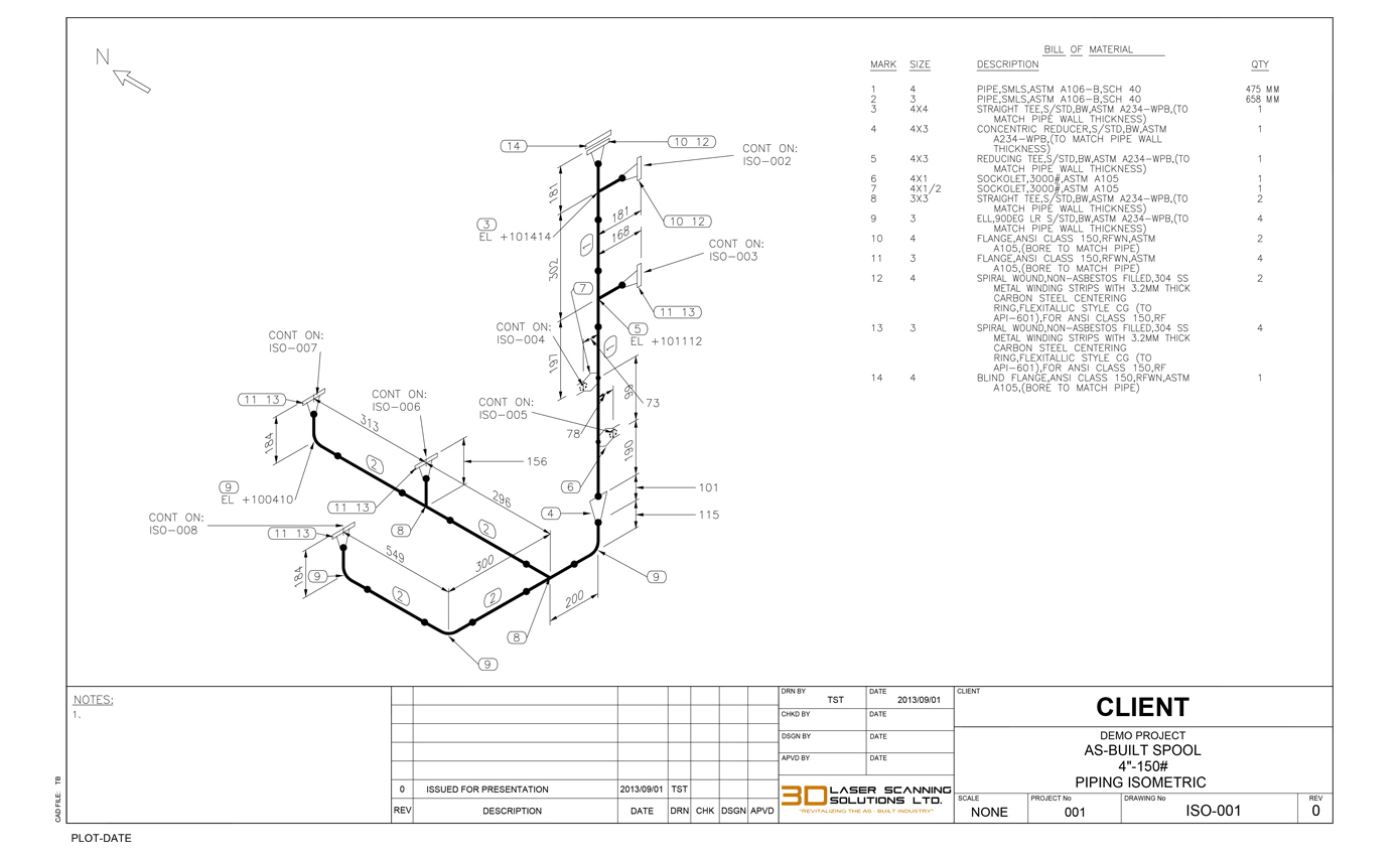
Teknologi dan Perencanaan Sistem Perpipaan by Ir. Usually, FFW will occur at the nozzle of equipment or tie-in locations.Īmerican Petroleum Institute (API) standards, Petronas Technical Specification (PTS), Shells Design Engineering Practices (DEP), American Society of Mechanical Engineer (ASME), and American Society for Testing and Materials (ASTM), etc. This FFW is defined by the designer if heshe could foresee that the spool might require some adjustment before the final fit-up, so at the location of FFW has been marked, it will be given some pipe length tolerance (commonly 150-300mm). There is one more type of weld that is known as field-fit weld (FFW). The complete piping system is separated into pieces that is transported to the site for erection. The dimensions in Isometric drawings are measured from the pipe centreline and not from the outer diameter of the pipe (refer to the image attached below for reference).įor example, if double piping is modeled by mistake, it will read double quantity of material. In the example given, take the flow from x, the pipe goes up then up-northwest then north.Īs you get along with Iso a lot, things will come naturally. It could help you in having a better understanding of which axes the pipe travel and how the piping should look like. In order to check the dimension of pipe length with offset, common Pythagorass theorem and Trigonometric rule can be used. In such cases, piping design may land on Northeast, Southeast, Northwest or Southwest axes. 
This basic imagination is required for the piping having an offset.Ī popular use is a 45-degree elbow and this is used extensively in piping design.

In recent days, the 3D models could automatically extract the Isometric by a single click of a mouse. With innovation and advancement of the digital age, isometrics are drawn by AutoCADMicrostation software. Imagine complex design and yet orthographic drawings are used for construction, that is really a headache. The actual sizes are notified in Bill of Material, tagging, call-out or notes. Pipes are drawn with a single line irrespective of the line sizes, as well as the other configurations such as reducers, flanges, and valves.


 0 kommentar(er)
